A robot called p1x37

IOT mandatory assignment

By Allan Nielsen & Mads Veelsgaard Nielsen


Vores problemstilling erKan vi sende kommandoer fra en computer til vores Rapiro og fjernstyre den.
Idéer

  • Webservice
    Vores første idé var at vi havde muligheden for at kontrollere flere robotter igennem internet vha. en webservice. Vi havde ikke nok viden til at kunne lave det, og vi fandt ud af at det ville tage for lang tid at skulle til at programmere på så kort tid.


  • PS4 controller
    Vi tilslutter vores PS4 controller til en bærbar og via UDP forbinder vi til en raspberry pi3 i Rapiroen, vi bruger en client-server arkitektur, hvor computeren med vores controller er client og raspberry pi’en er vores server.

Konklusion

Vi fik lavet vores Rapiro og udført nogle commands via dens tilhørende Arduino SDK.
Vi fik lavet en client server-arkitektur, vi har fået forbindelse til vores server ved at sende en simpel streng til vores raspberry Pi fra computeren. Vi har arbejdet ud fra et Python script til en PS4 controller, som skulle oversætte kommandoer fra Playstation controlleren til en enkel måde at bearbejde dataen, med Python.
Vi fik besvær med at få forbindelsen mellem Raspberry Pi’en og Arduino’en og har derved ikke fået testet om Python scriptet er kompatibel med Arduino’en.


UDP Client

#! /usr/bin/env python

import socket

UDP_IP = "192.168.0.102"
UDP_PORT = 6789
MESSAGE = "Hello, World!"


print("UDP target IP:", UDP_IP)
print("UDP target port:", UDP_PORT)
print("message:", MESSAGE)

sock = socket.socket(socket.AF_INET, socket.SOCK_DGRAM)
sock.sendto(MESSAGE.encode(), (UDP_IP, UDP_PORT))


UDP Server

#! /usr/bin/env python

import socket
import serial

UDP_PORT = 6789

server = socket.socket(socket.AF_INET, socket.SOCK_DGRAM)

server.bind(("", UDP_PORT))

# ser = serial.Serial('/dev/tty.usbserial', 9600)
# ser.write(b'5')

while True:
    data, addr = server.recvfrom(1024) # buffer size is 1024 bytes
    print("received message:", data)


PsController

#! /usr/bin/env python

import os
import platform
import pprint
import pygame
import socket


class PS4Controller(object):
    """Class representing the PS4 controller. Pretty straightforward functionality."""
    controller = None
    axis_data = None
    button_data = None
    hat_data = None

    command = "!M0"

    def init(self):
        """Initialize the joystick components"""
        pygame.init()
        pygame.joystick.init()
        self.controller = pygame.joystick.Joystick(0)
        self.controller.init()

    def listen(self):
        """Listen for events to happen"""
        if not self.axis_data:
            self.axis_data = {}

        if not self.button_data:
            self.button_data = {}
            for i in range(self.controller.get_numbuttons()):
                self.button_data[i] = False

        if not self.hat_data:
            self.hat_data = {}
            for i in range(self.controller.get_numhats()):
                self.hat_data[i] = (0, 0)

        while True:
            for event in pygame.event.get():
                if event.type == pygame.JOYAXISMOTION:
                    self.axis_data[event.axis] = round(event.value, 2)
                elif event.type == pygame.JOYBUTTONDOWN:
                    self.button_data[event.button] = True
                elif event.type == pygame.JOYBUTTONUP:
                    self.button_data[event.button] = False
                elif event.type == pygame.JOYHATMOTION:
                    self.hat_data[event.hat] = event.value

                """
                command	        action	                    eye color
                -----------------------------------------------------
                #M0	            Stop	                    Blue
                #M1	            Move Forward	            Blue
                #M2	            Move Back	                Blue
                #M3	            Turn right	                Blue
                #M4	            Turn left	                Blue
                #M5	            Wave both hands	            Green
                #M6	            Wave right hands	        Yellow
                #M7	            Grip both hands	            Blue
                #M8	            Wave left hand	            Red
                #M9	            Stretch out right hand	    Blue
                """

                """
                CONTROL DEFAULT MODE
                """
                # conditions = self.button_data == BCP.no_action() and self.axis_data == ACP.no_action() and self.hat_data == DCP.no_action()
                # if conditions:
                #     command = "!M0"
                #     print(command)

                """
                BUTTONS
                """
                if self.button_data[0]:
                    command = "!M6"
                    print(command)
                elif self.button_data[1]:
                    command = "!M5"
                    print(command)
                elif self.button_data[2]:
                    command = "!M7"
                    print(command)
                elif self.button_data[3]:
                    command = "!M8"
                    print(command)
                elif self.button_data[4]:
                    command = "!M9"
                    print(command)
                elif self.button_data[5]:
                    return
                elif self.button_data[6]:
                    return
                elif self.button_data[7]:
                    return
                elif self.button_data[8]:
                    return
                elif self.button_data[9]:
                    return
                elif self.button_data[10]:
                    command = "!M0"
                    print(command)
                elif self.button_data[11]:
                    return
                elif self.button_data[12]:
                    return

                """
                ANALOG
                """
                if self.axis_data[0]:
                    command = "!M1"
                    print(command)
                elif self.axis_data[2]:
                    command = "!M2"
                    print(command)
                elif self.axis_data[3]:
                    command = "!M4"
                    print(command)
                elif self.axis_data[4]:
                    command = "!M3"
                    print(command)
                elif self.axis_data[5]:
                    return
                elif self.axis_data[6]:
                    return
                elif self.axis_data[7]:
                    return
                elif self.axis_data[8]:
                    return
                elif self.axis_data[9]:
                    return
                elif self.axis_data[10]:
                    return

                """
                D-PAD
                """
                if self.hat_data[0]:
                    return
                elif self.hat_data[1]:
                    return
                elif self.hat_data[2]:
                    return
                elif self.hat_data[3]:
                    return
                #
                if platform.system() == "Linux":
                    os.system('clear')
                else:
                    os.system('cls')

                pprint.pprint(self.button_data)    # Buttons
                pprint.pprint(self.axis_data)      # Analog sticks
                pprint.pprint(self.hat_data)       # D-Pad

if __name__ == "__main__":
    ps4 = PS4Controller()
    ps4.init()
    ps4.listen()

På nuværende tidspunkt er koden ikke fuldt funktionel, men vi har tænkt os at få PsController.py til at virke i nærmeste fremtid.

https://github.com/Allando/p1x37-ISRW1

–Team Mad-lan
Thief Detector

What your tried the goal of your experiment?

We came up with an idea of making a small “security system” which is based in to 3 different modules. The main one is the camera and the other two are motion detector and the ultrasonic module.

So the idea of this combination of modules and sensors is to detect the movement of a person and take a snap and the ultrasonic module will measure the distance from the person to the camera (because the ultrasonic module will be next to it).

What we couldn’t achieve? We wanted to make it send a picture and distance details to an email but we were not able to implement it on time all of it.

One thing that needs to be mentioned is that the camera will stay on ‘sleep mode’ until a movement will trigger the motion detector, respectively the camera and the ultrasonic module.

During the implementation we had some problems with the camera which was not stopping after starting, but we could figure out the problem and fixed it on time.


Identify who have done the different parts: We have worked all the time together using pair programming technique so we cannot actually identify the specific pieces of code that each one has implemented or the modules connections.

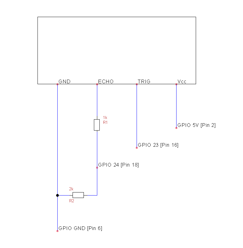
The UltraSonic range sensor was connected using this scheme :

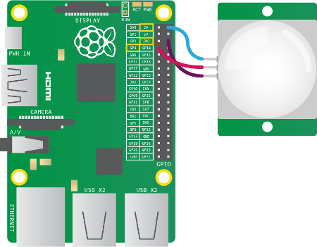
It requires the use of two resistors ,which we bought ourselves.Next up is the schema for the PIR Sensor(Motion detector):

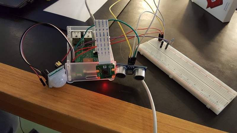
Combining these two sensors with the Camera Module we made this :

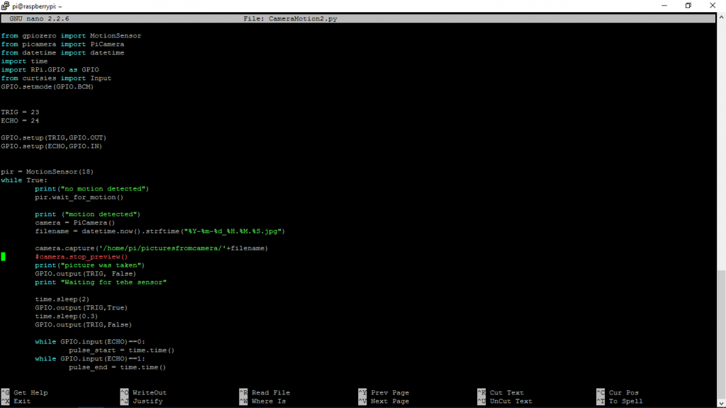
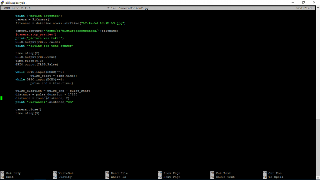
This is the code that runs on Raspberry Pi it waits for motion detection.If it detects motion it take a picture and measures the distance from the RPi.

C.R.A.P. (Controlled Rapiro Analog Project)

Who are we?

Dan Hansen, Karsten Darré og Mads Kristensen

Quest: To make a Rapiro robot move with input from an analog controller.

We started working with the Rapiro robot and found out that the Rapiro uses an Arduino board as its mainboard. The movement code can be found on their gitHub and then can be uploaded via USB to the mainboard.

Now we could send movement commands via our PC and needed to figure out how to do it from our Raspberry Pi. We had a lot of troubles with this because the internet only provided information on how to connect with python 2.7, and we were coding in python 3.

At first we thought that we could wire the Rapiro to our Pi’s pins, but this didn’t seem to work. We then came up with the idea to use serial messaging because we knew that it worked based on the experience from the computer.

Here you can see the code for the basic serial connection from the Pi’s USB port to the Rapiro mainboard:

import serial
import smbus

bus = smbus.SMBus(1)

ser=serial.Serial('/dev/ttyUSB0', 57600)

ser.write("$M0".encode('utf-8))

Now that we could send movement messages from our Pi we wanted to implement an analog controller for increasing the usability. We had some code from an earlier project with an analog controller which we combined with our serial connection.

Here you can see how it is combined:

import serial
import smbus
import time

bus = smbus.SMBus(1)

ser=serial.Serial('/dev/ttyUSB0', 57600)

while True:
    time.sleep(0.1)
    # Read analog - X-Akse
    bus.write_byte(0x48, 0x00)
    falseReadX = bus.read_byte(0x48)
    readingX = bus.read_byte(0x48)
    
    if (readingX > 130):
        ser.write("$M4".encode('utf-8'))
        # print data
        print("Højre")
    if (readingX < 100):
        ser.write("$M3".encode('utf-8'))
        # print data
        print("Venstre")

    # read analog - Y-Akse
    bus.write_byte(0x48, 0x01)
    falseReadY = bus.read_byte(0x48)
    readingY = bus.read_byte(0x48)
    
    if (readingY > 130):
        ser.write("$M2".encode('utf-8'))
        # print data
        print("Tilbage")
    if (readingY < 100):
        ser.write("$M1".encode('utf-8'))
        # print data
        print("Frem")

    # read analog - Knap
    bus.write_byte(0x48, 0x02)
    falseReadKnap = bus.read_byte(0x48)
    readingKnap = bus.read_byte(0x48)
    # if else if knap
    if (readingKnap > 230):
        ser.write("$M6".encode('utf-8'))
        # print data
        print("function")
    
    if (readingY < 130 and readingY > 100 and readingX < 130 and readingX > 100):
       ser.write("$M0".encode('utf-8'))


When this was working we thought i would be funny to make wireless controls instead. We divided the code in two parts – A sender and a reciever. We used UDP for this solution because it’s fast and easy.

Sender:

import smbus
import time
import socket

bus = smbus.SMBus(1)

remote_ip = "192.168.3.14" #Robot IP

UDP_IP = "192.168.3.205" #Sender IP
UDP_PORT = 5005


suck = socket.socket(socket.AF_INET, socket.SOCK_DGRAM)


while True:
    time.sleep(0.1)
    # Read analog - X-Akse
    bus.write_byte(0x48, 0x00)
    falseReadX = bus.read_byte(0x48)
    readingX = bus.read_byte(0x48)
    # if else if for readingX
    if (readingX > 130):
        suck.sendto(bytes(str("readingX,150"),'utf-8'),(remote_ip, UDP_PORT))
        # print data
        print("Højre")
    if (readingX < 100):
        suck.sendto(bytes(str("readingX,50"),'utf-8'),(remote_ip, UDP_PORT))
        # print data
        print("Venstre")
   
    # read analog - Y-Akse
    bus.write_byte(0x48, 0x01)
    falseReadY = bus.read_byte(0x48)
    readingY = bus.read_byte(0x48)
    # if else if for readingY
    if (readingY > 130):
        suck.sendto(bytes(str("readingY,150"),'utf-8'),(remote_ip, UDP_PORT))
        # print data
        print("Tilbage")
    if (readingY < 100):
        suck.sendto(bytes(str("readingY,50"),'utf-8'),(remote_ip, UDP_PORT))
        # print data
        print("Frem")

    # read analog - Knap
    bus.write_byte(0x48, 0x02)
    falseReadKnap = bus.read_byte(0x48)
    readingKnap = bus.read_byte(0x48)
    # if else if knap
    if (readingKnap > 230):
        suck.sendto(bytes(str("button,250"),'utf-8'),(remote_ip, UDP_PORT))
        # print data
        print("function")

    if (readingY < 130 and readingY > 100 and readingX < 130 and readingX > 100 and readingKnap < 200):
        suck.sendto(bytes(str("STOP"),'utf-8'),(remote_ip, UDP_PORT))


Reciever:

import serial
import socket
import time

ser=serial.Serial('/dev/ttyUSB0', 57600)


UDP_PORT = 5005

suck = socket.socket(socket.AF_INET, socket.SOCK_DGRAM)
suck.bind(("192.168.3.14",UDP_PORT))

while True:
   data, addr = suck.recvfrom(1024)
   data = data.decode('utf-8')
   
   #Analog X
   if data.startswith("readingX"):
      readX = data.split(",")
      if int(readX[1]) > 130:
         #Turn Right
         ser.write("$M4".encode('utf-8'))
      if int(readX[1]) < 100:
         #Turn Left
         ser.write("$M3".encode('utf-8'))
   #Analog Y
   if data.startswith("readingY"):
      readY = data.split(",")
      if int(readY[1]) > 130:
         #Go back
         ser.write("$M2".encode('utf-8'))
      if int(readY[1]) < 100:
         ser.write("$M1".encode('utf-8'))

   #Button
   if data.startswith("button"):
      readB = data.split(",")
      if int(readB[1]) > 230:
         #Wave
         ser.write("$M6".encode('utf-8'))

   #Stand still
   if data.startswith("STOP"):
      ser.write("$M0".encode('utf-8'))
      print(data)

#RobotDads

Mandatory Assignment – making a warlock game

Written by Christoffer Jepsen, Thomas Petersen and Miki Møller.

Project description:

The idea with this project is to re-create the game from warcraft 3 called “Warlocks”, in which we focus on the usage of joystick and a numpads, whilst also support 2 player functions.

The joystick is meant to be your aiming controller and the numpad is your movement and fire pad. It will be possible to read about how we approached this issue and what solutions we came up with on the run.

Initial setup: http://imgur.com/a/GbYqQ (4x pictures of our setup)

We had to cram down 2x numpads, 2x joysticks on the raspberry pi. A potential problem we thought we would dump into was that their was

only 2x 5v spots, in turned out that it did not matter if it was a 5V spot or 3,3V spot, it did not affect the project.


If we take a look at picture 5 you will see how we connected the connector with the joysticks. The different ports determines which bus we read on. The joysticks is also connected with ground and volt.

The numpads are connected with 8 different ports each, you might feel like you are running out of space and that it is messy, but just keep your head cool and you should be able to clean it up and understand where which port goes. The numpad number one (picture 4 green circle) is correctly connected, but numpad number 2(picture 4 blue circle) does not seem to be working completely correctly, since the first row with 1,4,7,* does not work, we worked around this by coding around it, but please do be mindful of this.

Picture 1-3 are mostly meant as a reference point in which you can see how the full setup is when put together.

Coding in Unity with C#

To visualize the player we use the unity3D Engine. As for scripting in unity we use C#.

In our unity view we got an empty game object with the UdpServer.cs. Here we handle incoming connections. The incoming message is split using the substring method. And is handled with a switch statement to set the values for the game. Here is a snippet of the part handing player one and two’s X and Y on joysticks direction. The subtract part is to calibrate to fit the joysticks default position if its not moved.

string messageSubstring = message.Substring(0, 2);
                switch (messageSubstring)
                {
                    case "1X":
                        MovePlayer1.P1XAimDir = int.Parse(message.Substring(2)) - 81;
                        break;
                    case "1Y":
                        MovePlayer1.P1YAimDir = int.Parse(message.Substring(2)) - 86;
                        break;
                    case "2X":
                        MovePlayer2.P2XAimDir = int.Parse(message.Substring(2)) - 123;
                        break;
                    case "2Y":
                        MovePlayer2.P2YAimDir = int.Parse(message.Substring(2)) - 133;
                        break;
                    default:
                        Debug.Log("Invalid syntax sent, this was the message: "+ messageSubstring);
                        break;
                }


We got a game object with a player1 with a player1.cs script and equally for player two. They both contain a lot of static variables containing everything about this player like if its keypad is pressed up or not.

To show which way the player is facing we’ve attached a child object with the model of an arrow to the player parent so when it rotates it rotates with it.

To get the facing we make a vector using the joystick input, we already calibrated it to have a default value that is close to zero.

Then we rotate the player

  P1CurrentFacing = new Vector3(P1XAimDir, 0, P1YAimDir);
        transform.rotation = Quaternion.LookRotation(P1CurrentFacing);


To move the player we do as follows. This is if the player moves up that is the 2 on the keypad is pressed. We use translate to this and use the build in  vector for up called forward. And then we times it with the  basespeed which Is the speed we want it to move with. The Space.World perametere is important to say it translates according to its universal position in the game and not its local.

  if (p1w == true)
        {
            transform.Translate(Vector3.forward * Time.deltaTime * baseSpeed,Space.World);   
        }


To shoot the fireball we have another if statement. It instantiates a new game object of our fireballprefab with our player’s initial position and facing

The fireball has its own script to move and check if it hits

When someone is hit we cannot use a normal loop as that would halt the entire project and move the player in one frame but we have something called Coroutine to use this we make a IEnumerator function and start it using the StartCoroutine. It runs the code but when it reaches “yield return null;” it stops its execution for this frame and continues from were it left in the next. 

Main.py

Imports and variables

We import different functionality.

  • Time, this is used in our case to do delays to control how often something is sent or registered.
  • Socket, this is used for the udp server. Without this we can’t sent or receive data.
  • GPIO as GPIO, this is what controls the inputs on the RaspberryPi, and allows us to see and change inputs/outputs on the pins.
  • Matrixkey is a method we built ourselves, and I will be going into detail about it later in this document.
  • From smbus import SMBus, this Is used to read and write to the GPIO ports.


UDP_IP is just an ip address.

UDP_PORT is the port we use.

UDP_INFO is the two above combined

Sock is the socket.

def Main()

This function is used as the entry point for the program.

def GetPInput()

In this function we listen for inputs on the different pins we use.

        if player == "1": #Player one
                #Get Y-Axis
                bus.write_byte(0x48, 0x03)
                bus.read_byte(0x48)
                ValueY = bus.read_byte(0x48)
                #Get X-Axis
                bus.write_byte(0x48, 0x01)
                bus.read_byte(0x48)
                ValueX = bus.read_byte(0x48)
                #Keypad         
                v = MatrixKey.KeypadInput()
                print(v)

The if is to see whether we are looking for the player one or player two inputs. Bus.write.byte is to determine what input we are looking for. Then we look at the input and put this into the ValueY variable. The same is done for the ValueX. The MatrixKey is to look at the keypad input, this will be looked at later. Last we print what the MatrixKey value is.

    else:
                print("Player number out of range.")

This is just for errorhandling. Not really that important.

        ReturnAllValues = [player+"X"+str(ValueX), player+"Y"+str(ValueY), player+'K'+str(v)]
        return ReturnAllValues

This takes all the information and creates one variable with all of it in one. Then it adds some protocol letters so the recipient of the message can distinguish between player one and two.

def UdpServer():
        #The try is to make sure we don't hog all the ports, and close the connection in a 'nice way'.
        try:
                print("Server Started")
                while True:
                        #Player 1 is "1" and player 2 is "2", quite simple.
                        playerOne = GetPInput("1")
                        playerTwo = GetPInput("2")
                        #time.sleep(0.5)
                        for x in range(0, len(playerOne)):
                                time.sleep(0.05)
                                sock.sendto(bytes(playerOne[x].encode()), (UDP_IP, UDP_PORT))
                        #time.sleep(0.1)
                        for x in range(0, len(playerTwo)):
                                time.sleep(0.05)
                                sock.sendto(bytes(playerTwo[x].encode()), (UDP_IP, UDP_PORT))
                                print(playerTwo[x])

        except KeyboardInterrupt:
                print("Connection Closed")
                sock.close()

This is the udp server. This works by trying to send the data from the GetPInput with the parameter determining what player we want to see the input from. Then we send the bytes from the players over udp to the unity server. This all happens in a while loop to make sure it keeps happening. We have made an exception that handles when you do keyboard interruptions because we wanted to be able to shut down the service.

if __name__=="__main__":
        Main()


This is to make sure the Main() function is called.

def KeypadInput()

        GPIO.setmode(GPIO.BCM)
        GPIO.setwarnings(False)
        MATRIX = [ [1,2,3,'A'],
                 [4,5,6,'B'],
                 [7,8,9,'C'],
                 ['*',0,'#','D'] ]

        ROW = [5,6,13,19]
        COL = [26,16,20,21]

In this function we start out by setting up a couple of variables and settings. The GPIO.setmode determines whether we are looking at all the pins or some specific pins.

The matrix is the keypad setup.

The ROW and COL are determining what pins are used for what row and what column on the keypad.

for j in range(4) :
                GPIO.setup(COL[j], GPIO.OUT)
                GPIO.output(COL[j], 1)

        for i in range(4) :
                GPIO.setup(ROW[i], GPIO.IN, pull_up_down = GPIO.PUD_UP)


        try:
                for j in range(4) :
                        GPIO.output(COL[j],0)
                        for i in range(4) :
                                if GPIO.input(ROW[i]) == 0:
                                        return (str(MATRIX[i][j]))
                                        while(GPIO.input(ROW[i]) == 0) :
                                                pass
                GPIO.output(COL[j],1)
        except KeyboardInterrupt:
                GPIO.cleanup()
        finally:
                GPIO.cleanup()

Now we get to the code that register the buttons that are being pressed. The first for loop sets up the pins. The following for loops looks at what rows and columns are being pressed, this way it can calculate what button and thus what char is being pressed.


Finally we have som keyboardinterrupt to make sure it cleans up after use.


Robot car with stepper motors. Tomas, Alexander and Mikkel 2017 IoT

We have been working with the robot car using 2x stepper motors. We started out by figuring out how to setup the hardware, using a raspberry pi a BCM board and the stepper motors. We connected the stepper motors to the board and the board to the raspberry pi.

On the picture of the raspberry pi we used these pins for each motor:

ControlPin = [4,14,15,18]
ControlPin2 = [19,16,20,21]

View post on imgur.com

Robotcar board

Be aware that hardware problems can appear, we experienced this, once with some caples not working and a driver (The little red board that are connected to the stepper motor) also we tried that our raspberry pi did not work.

When we got the hardware setup we thought about our intentions with the project, where we agreed that in the end we should be able to control it by using a laptop keyboard with the function of turning left and right as well as moving forward and backwards. We decided to use the W (forward) A ( left) S (backwards) D (right)  Z(backwards left) X(backwards right)
Before we started using keys to control our stepping motors we tried to make them drive without them just to make it work, by using two sequence code. Each of the controls were use to make the 2 motors move forward and backward, the reason we use 2 was because our motors was placed mirrored for each other.

This is the 2 sequences we used:

seq = [ [1,0,0,0],
        [1,1,0,0],
        [0,1,0,0],
        [0,1,1,0],
        [0,0,1,0],
        [0,0,1,1],
        [0,0,0,1],
        [1,0,0,1] ]

seq2= [ [1,0,0,1],
        [0,0,0,1],
        [0,0,1,1],
        [0,0,1,0],
        [0,1,1,0],
        [0,1,0,0],
        [1,1,0,0],
        [1,0,0,0] ]

After that we made our 4 definition for which way to wheels should move by using the 2 seg controls. Like our seg are 2 definition of each of our motors made 1 for forward and 1 for backward

def loop_fr():
        for i in range(512):
                for halfstep in range(8):
                        for pin in range(4):
                                GPIO.output(ControlPin2[pin], seq2[halfstep][pin])
                        time.sleep(0.001)

def loop_fl():
        for x in range (512):
                for halfstep in range(8):
                        for pin in range(4):
                                GPIO.output(ControlPin[pin], seq[halfstep][pin])
                        time.sleep(0.001)


def loop_br():
        for i in range(512):
                for halfstep in range(8):
                        for pin in range(4):
                                GPIO.output(ControlPin2[pin], seq[halfstep][pin])
                        time.sleep(0.001)

def loop_bl():
        for i in range(512):
                for halfstep in range(8):
                        for pin in range(4):
                                GPIO.output(ControlPin[pin], seq2[halfstep][pin])
                        time.sleep(0.001)

Before we got it moving with the arrow keys, we used threads and joined them to get the 2 motors to run at the same time ( we did continue using these later on also) but we had to execute each part of the program to make the wheels move.

The way we found the value for the keyboard keys was using this code which allowed us to see which value the key we press was.

char = screen.getch()
print(char) #used to find value of a keypress

When we had found the values for the keys we wanted to use we proceed to make a while true loop where we was going to control which way the car would move. the code contains if statements which each are use to make the car move a specific way by pressing the key.

We are using 2 different if statements, for moving forward and backward we are using threads to make the 2 motors to run at the same time and another statement to make it turn left or right

while True:
        char = screen.getch()
        #print(char) #used to find value of a keypress
        if (char==100):
                print ('Right') #Key D
                loop_fr()
        if (char==97):
                print('Left') # Key: A
                loop_fl()
        if (char==122):
                print('Back left') #Z
                loop_bl()
        if (char==120):
                print('Back right') #X
                loop_br()
        if (char==119):
                print ('Forward')#W
                threadA=Thread(target=loop_fr)
                threadB=Thread(target=loop_fl)
                threadA.start()
                threadB.start()
		threadA.join()
                threadB.join()
        if (char==115):
                print('Back') #S
                threadD=Thread(target=loop_br)
                threadC=Thread(target=loop_bl)
                threadD.start()
                threadC.start()
                threadD.join()
                threadC.join()
        if (char==32):
                threadA=Thread(target=loop_fr)
                threadC=Thread(target=loop_bl)
                threadA.start()
                threadC.start()
                threadA.join()
                threadC.join()
                print('breakdance!')
#breackdance code is for turning at one point without moving forward at the same time.

GPIO.cleanup()


The complete code is inserted under this:

import RPi.GPIO as GPIO
import time
from threading import Thread
import curses
import getch

GPIO.setmode(GPIO.BCM)
screen = curses.initscr()
ControlPin = [4,14,15,18]
ControlPin2 = [19,16,20,21]

for pin in ControlPin:
        GPIO.setup(pin,GPIO.OUT)
        GPIO.output(pin,0)

for pin in ControlPin2:
        GPIO.setup(pin,GPIO.OUT)
        GPIO.output(pin,0)


seq = [ [1,0,0,0],
        [1,1,0,0],
        [0,1,0,0],
        [0,1,1,0],
        [0,0,1,0],
        [0,0,1,1],
        [0,0,0,1],
        [1,0,0,1] ]

seq2= [ [1,0,0,1],
        [0,0,0,1],
        [0,0,1,1],
        [0,0,1,0],
        [0,1,1,0],
        [0,1,0,0],
        [1,1,0,0],
        [1,0,0,0] ]

def loop_fr():
        for i in range(512):
                for halfstep in range(8):
                        for pin in range(4):
                                GPIO.output(ControlPin2[pin], seq2[halfstep][pin])
                        time.sleep(0.001)

def loop_fl():
        for x in range (512):
                for halfstep in range(8):
                        for pin in range(4):
                                GPIO.output(ControlPin[pin], seq[halfstep][pin])
                        time.sleep(0.001)

def loop_br():
        for i in range(512):
                for halfstep in range(8):
                        for pin in range(4):
                                GPIO.output(ControlPin2[pin], seq[halfstep][pin])
                        time.sleep(0.001)

def loop_bl():
        for i in range(512):
                for halfstep in range(8):
                        for pin in range(4):
                                GPIO.output(ControlPin[pin], seq2[halfstep][pin])
                        time.sleep(0.001)


text = ('W=Forward, A=Left, D=Right, S=Back, Z=Back Left, X=Back Right')
print(text)

while True:
        char = screen.getch()
        #print(char) #used to find value of a keypress
        if (char==100):
                print ('Right')
                loop_fr()
        if (char==97):
                print('Left')
                loop_fl()
        if (char==122):
                print('Back left')
                loop_bl()
        if (char==120):
                print('Back right')
                loop_br()
        if (char==119):
                print ('Forward')
                threadA=Thread(target=loop_fr)
                threadB=Thread(target=loop_fl)
                threadA.start()
                threadB.start()
		threadA.join()
                threadB.join()
        if (char==115):
                print('Back')
                threadD=Thread(target=loop_br)
                threadC=Thread(target=loop_bl)
                threadD.start()
                threadC.start()
                threadD.join()
                threadC.join()
        if (char==32):
                threadA=Thread(target=loop_fr)
                threadC=Thread(target=loop_bl)
                threadA.start()
                threadC.start()
                threadA.join()
                threadC.join()
                print('breakdance!')

GPIO.cleanup()


SmartLock by TheWildHest

We have made a SmartLock that can be locked and unlocked through the click of a button on a website, using the raspberry pi.
To begin with we had some troubles gaining access to dev/mem and dev/gpiomem. In step 4 below our solution to that problem is shown.

1)  We installed Apache and PHP on the Pi.
2) We made sure that Apache supported PHP.
3) We hosted our website on the Raspberry Pi using Apache.
4) We gave “www-data” (profile) access to dev/mem and dev/gpiomem. This is done in the terminal by writing:
chmod 777 dev/mem
chmod 777 dev/gpiomem
5) We accessed the website using the Pi’s IP address.

Proof of concept:

Fritzing:

SmartLockFritz_bb

Code:
move.py
credit to;
https://github.com/christophrumpel/test_stepper/blob/master/stepper_library.py

from time import sleep
import RPi.GPIO as GPIO

class Motor(object):
    def __init__(self, pins):
        """Initialise the motor object.

        pins -- a list of 4 integers referring to the GPIO pins that the IN1, IN2
                IN3 and IN4 pins of the ULN2003 board are wired to
        """
        self.P1 = pins[0]
        self.P2 = pins[1]
        self.P3 = pins[2]
        self.P4 = pins[3]
        self.deg_per_step = 5.625 / 64  # for half-step drive (mode 3)
        self.steps_per_rev = int(360 / self.deg_per_step)  # 4096
        self.step_angle = 0  # Assume the way it is pointing is zero degrees
        for p in pins:
            GPIO.setup(p, GPIO.OUT)
            GPIO.output(p, 0)

    def _set_rpm(self, rpm):
        """Set the turn speed in RPM."""
        self._rpm = rpm
        # T is the amount of time to stop between signals
        self._T = (60.0 / rpm) / self.steps_per_rev

    # This means you can set "rpm" as if it is an attribute and
    # behind the scenes it sets the _T attribute
    rpm = property(lambda self: self._rpm, _set_rpm)

    def move_to(self, angle):
        """Take the shortest route to a particular angle (degrees)."""
        # Make sure there is a 1:1 mapping between angle and stepper angle
        target_step_angle = 8 * (int(angle / self.deg_per_step) / 8)
        steps = target_step_angle - self.step_angle
        steps = (steps % self.steps_per_rev)
        if steps > self.steps_per_rev / 2:
            steps -= self.steps_per_rev
            print "moving " + `steps` + " steps"
            self._move_acw_2(-steps / 8)
        else:
            print "moving " + `steps` + " steps"
            self._move_cw_2(steps / 8)
        self.step_angle = target_step_angle

    def __clear(self):
        GPIO.output(self.P1, 0)
        GPIO.output(self.P2, 0)
        GPIO.output(self.P3, 0)
        GPIO.output(self.P4, 0)
#Counter clockwise
    def _move_acw_2(self, big_steps):
        self.__clear()
        for i in range(big_steps):
            GPIO.output(self.P3, 0)
            GPIO.output(self.P1, 1)
            sleep(self._T * 2)
            GPIO.output(self.P2, 0)
            GPIO.output(self.P4, 1)
            sleep(self._T * 2)
            GPIO.output(self.P1, 0)
            GPIO.output(self.P3, 1)
            sleep(self._T * 2)
            GPIO.output(self.P4, 0)
            GPIO.output(self.P2, 1)
            sleep(self._T * 2)
#Clockwise
    def _move_cw_2(self, big_steps):
        self.__clear()
        for i in range(big_steps):
            GPIO.output(self.P4, 0)
            GPIO.output(self.P2, 1)
            sleep(self._T * 2)
            GPIO.output(self.P1, 0)
            GPIO.output(self.P3, 1)
            sleep(self._T * 2)
            GPIO.output(self.P2, 0)
            GPIO.output(self.P4, 1)
            sleep(self._T * 2)
            GPIO.output(self.P3, 0)
            GPIO.output(self.P1, 1)
            sleep(self._T * 2)

    def unlock(self):
        self.move_to(-90)


    def lock(self):
        self.move_to(90)

lock.py

from move import Motor
import RPi.GPIO as GPIO


GPIO.setmode(GPIO.BOARD)

motor = Motor([18,22,24,26])
motor.rpm = 10

motor.lock()

print('locked')

GPIO.cleanup()

lock.php

<?php

exec("python lock.py 2>&1",$out);


foreach($out as $value){
   echo $value;
}
?>

unlock.py

from move import Motor
import RPi.GPIO as GPIO

GPIO.setmode(GPIO.BOARD)

motor = Motor([18,22,24,26])
motor.rpm = 10

motor.unlock()

print('unlocked')

GPIO.cleanup()

unlock.php

<?php

exec("python unlock.py 2>&1",$out);


foreach($out as $value){
   echo $value;
}
?>

my.js

$(document).ready(function () {

$("#lockBtn").click(function () {
    if($(this).text() === 'Lock'){
        $(this).text('Unlock');
        $.get('unlock.php');
    } else {
        $(this).text('Lock');
        $.get('lock.php');
    }
});
});

    function lockoutSubmit(button) {
        var oldValue = button.value;

        button.setAttribute('disabled', true);
        button.value = '...processing...';

        setTimeout(function(){
            button.value = oldValue;
            button.removeAttribute('disabled');
        }, 3000)
    }

Project zip:
IOT_SmartLock_Website

Best practice when using Linux

Hi all,

Just wanted to add my two cents to using Linux on the Pi’s. If you use the following rules then you are most likely to not fuck up stuff – and you can in Linux, especially as root or with sudo (superuser do).


Recommendations:

  • Don’t run as root. We don’t really need it for our work. The Pi user (or your own if you have created one) will suffice.
  • Don’t sudo unless you have to. Generally run commands without sudo first, if it doesn’t work without sudo you can type
  •  $ sudo !!
    

(which will run the last command you just did with sudo).

Why:

If you are not 100% sharp on what you do you can ruin the OS or features.

Fx:

$ sudo ifconfig eth0 down

will stop the Ethernet port from running. Good luck connecting to the Pi with a cable again (if ssh daemon is running you can connect through wifi and set eth0 up).


Usefull stuff:

  • Use “tab” key to autocomplete when using the CLI.
  • cd (change directory):
    • cd .. (go back one directory)
    • cd – (go back to the directory you came from)
    • cd ~ (go to /home/$YOUR_USER)
    • And many more.
  • Looking for something?
    • find -name “your_search” (finding files)
    • grep “your_search_pattern” (finding files or lines in files)
  • What is in this directory?
    • dir
    • ls
    • ls -lh
  • The CLI is smart. It can run one-line scripts:
    • for f in *.py; do echo “$f”; done
      • Will loop over all files in current working directory that is called “something”.py
  • Need more than one-line scripts?
    • Use bash
      • Create a file (e.g. touch “your_file”)
      • Edit the file and add:
      • #!/bin/bash

        at the top of the file

      • Add you script to the file
      • save the file and make it executable:
      • $ sudo chmod +x "your_file"
  • * (asteriks) is a wildcard – it can be anything.

4×4 Membrane keypad RPI

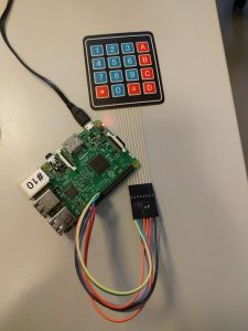
Device:

Source code:
source

import RPi.GPIO as GPIO
 
GPIO.setmode(GPIO.BCM)
 
MATRIX = [ [1,2,3,'A'],
           [4,5,6,'B'],
           [7,8,9,'C'],
           ['*',0,'#','D'] ]
 
ROW = [5,6,13,19]
COL = [26,16,20,21]
 
for j in range(4) :
        GPIO.setup(COL[j], GPIO.OUT)
        GPIO.output(COL[j], 1)
 
for i in range(4) :
        GPIO.setup(ROW[i], GPIO.IN, pull_up_down = GPIO.PUD_UP)
 
try:
        while(True) :
                for j in range(4) :
                        GPIO.output(COL[j],0)
 
                        for i in range(4) :
                                if GPIO.input(ROW[i]) == 0:
 
                                        print MATRIX[i][j]
                                        while(GPIO.input(ROW[i]) == 0) :
                                                pass
                        GPIO.output(COL[j],1)
except KeyboardInterrupt :
        GPIO.cleanup()


Pastebin: http://pastebin.com/gV9e466L

Fritzing PDF:
Keypad-4x4_RPi_wiring_bb

Get it to work:
1) Get access to RPI
2) Write: sudo nano
3) 
Paste the code from above into the text editor
4) Press CTRL+X
5) Press Y
6) Give the file a name Name.py
7) Press Enter
8) Write: python Name.py
9) Press Enter
10) Program is running.

Post by: Nicki, Rasmus & Thor